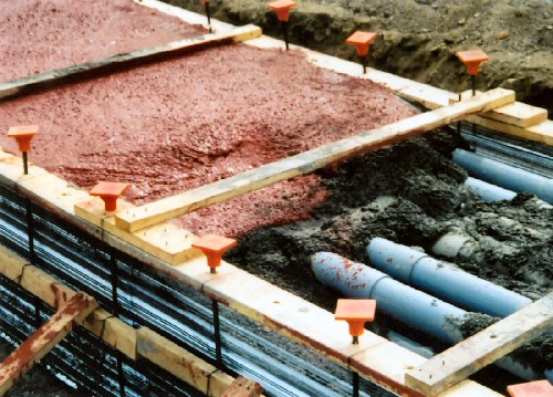
Debonding of FRP from the concrete substrate is a typical failure mode in such strengthened structures. The technique of externally bonding fiber-reinforced polymer (FRP) composites has become very popular worldwide for retrofitting existing reinforced concrete (RC) structures. It is proposed that the vertical displacement of concrete duct bank can be set as the monitoring item to reveal its safety state, and the minimum curvature radius of longitudinal deformation profile obtained from vertical settlement at different locations can be computed and be taken as the control index. The mechanical properties of underlying soil play a more dominant role in the bearing capacity, mid-span vertical displacement and mid-span deflection of concrete duct bank. Both the test and numerical results indicated that the failure of concrete duct bank presented a distinct brittle pattern. And then numerical simulations were performed for the 1/4 part of real structure and a real-scale concrete duct bank respectively, to investigate the deformation and damage pattern of concrete structure and the wrapped inside conduits. This paper briefly presents an experimental study of concrete duct bank with a 1/4 part of real structure under a monotonic static loading, which was put into a soil box in the laboratory.

The 750 derated at 0.80 x 475 amps = 380 amps x 20 runs = 7600 amps.Due to the shallow burial depth, the concrete duct bank for underground cables frequently encountered differential settlement, tilt and other damage like cracking when construction activity was carried out in the vicinity. If so, then a 0.80 derating factor must abe applied to the ampacity of the 750 conductor. If the assumptions that there is no harmonic load is incorrect, then 310.15.B(4)c requires that the neutral may be required to be counted as a current carrying conductor. However the posts states that there are some spares in the duct runs, therefore the total runs of 750 must be less than the assumes 20 and the ampacity is less that the 9500 amps. 20 runs of 750 at 475 amps equals a total of 9500 amps. Making another assumption that the load will not produce harmonic currents,Īn assumption that is likely incorrect, then theĪmpacity of the 750 at 75 degree equals 475 amps Since the duct runs are 24" apart, I do not think you will have mutual heating between the ducts.Īssuming that is correct, you can use table 310.16įor conductor ampacity. Each conduit has 3 750 phase conductor,Ī 750 neutral conductor and a 4/0 GND conductor. From your post it appears to me that you have 5 duct runs, each consisting of 4 4?" conduits for a total of 20 conduits.
CONCRETE ENCASED DUCT BANK DESIGN CODE
There are table in the 2002 code in Annex B


Is heat buildup and the loss of ampacity a concern? Is filling the void between banks w/concrete beneficial, or should the banks be individually formed?įirst, this is not a code issue. I apologize for trying to be succinct with my first post. Are there guidelines for the max number of conduit at "X" voltage that can be placed in a duct bank before heat becomes a problem? Heat dissipation has become an issue - but NEC '99 Article 310 does not offer any guidelines as to when heat build-up becomes a problem. Plans call for a "river" of concrete slurry to encase the conduit w/6" of slurry all around. The typical conduit has 4 - 750 KCMIL and 1 - #4/0 GND. The common duct bank from the service yard to the building has up to 20 - 4" conduit(incl spares)in five groups of 4's with 24" spacing in between and 18" cover. I have a large commercial project served by 3 - 3000A service sections for 277/480 3ph lighting and HVAC equipment.


 0 kommentar(er)
